Most additive manufacturing methods were designed for small scale prototype parts, but today the industry research is pushing towards larger scale manufacturing and stronger parts. Full scale cars and furniture have been printed with the constant challenge or time reduction and increased strength.
This reinforced printing nozzle allows the production of parts with a metal wire fed paralelle to the polymer Filament.
Inspired by profile extrusion technologies, this Concept nozzle uses a Standard design with an added insert. The insert shown below in Grey color allows the polymer to flow around it before reaching the hot end, and also allows through an Opening, a metal wire (or mesh) to be fed with the polymer.
Such adjusted nozzle design requires the grey insert and a special copper (or other) end with a hole at its side to allow the metal wire in.
Isolating the polymer in 3D view, you can see how the flow seperates into three streams and then connects again at the nozzle tip. The seperation of the polymer flow allow the polymer to heat faster as it increases the contact area with the nozzle.
Having this Special nozzle insert allows the increase of the extruded diameter or the final deposited width. Even without extruding a metal wire with the polymer, this nozzle can have a diameter much larger then the filament being fed. This feature is not possible with standard nozzles as the genral recommendation is a nozzle width of not more than half the filament diameter.
The last Picture above shows how the metal wire and the molten polymer meet before deposition. I think should Concept can have many application for large scale models and high strength requirements. The wire fed with the polymer can be of any other material including glass fiver and Carbon Fiber.
I would like to to know your opinion on such Concept ? Do you think there would be difficulty in printing ?
More than ten years of hype About the 3D printing Technology ,and it still faces the same Problems.Those Problems include , slow process, limited build volume, and reduced accuracy for larger parts.(properly named additive manufacturing)
The most common desk technology is the fused deposition manufacturing (FDM), this technology uses a plastic filament that is molten through a hot nozzle and deposited layer by layer to form a plastic part. Most printers in the market have a build area of 200x200 mm to 500x500 mm, with the larger Printers having less print accuracy and more problems with proper heat distribution on the heated bed.
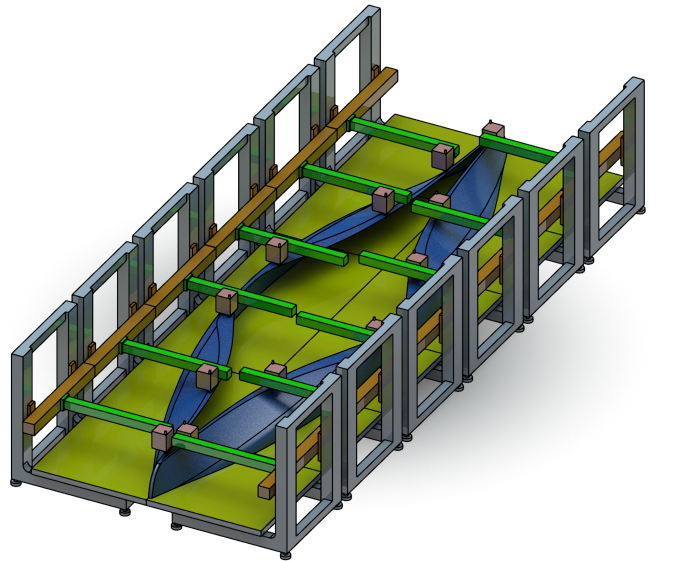
This is a simplified design of one cooperative Printer. This open side print bed combined with the possibility for the nozzle to travel few millimiters outside the build area, make this printer concept capable of depositing plastic on the build plate of an adjacent printer. so, why would that be usefull ?
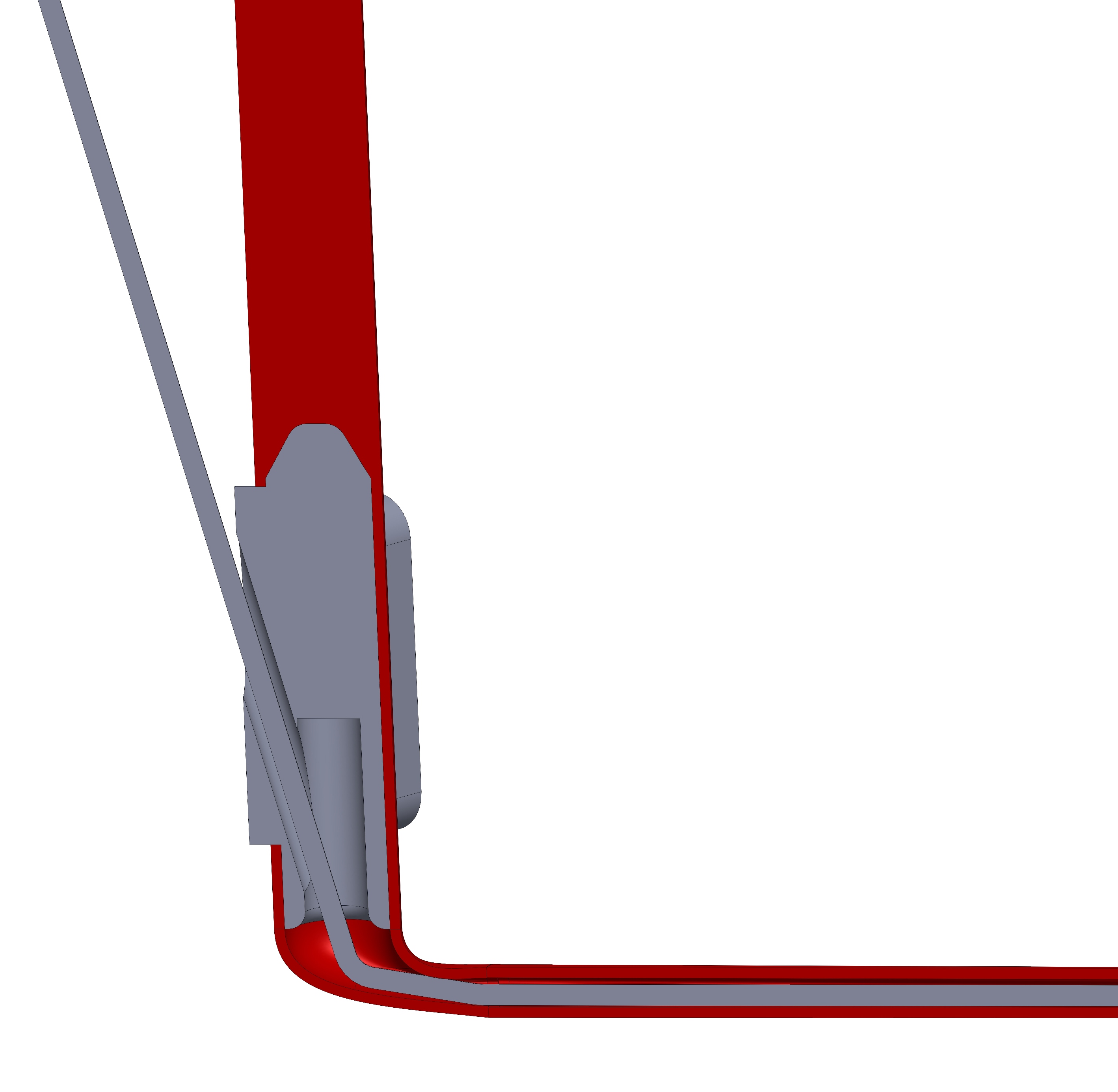
The printer can deposite a brick shaped layout or in other words a Zipper form attached layers, so whatever part is being build on the adjacent build plate is connected to the part on the main printer. The attached parts will have a layer interface as shown below. With a thickness to length ratio of more than 15 the parts will be properly bonded with enough strength. Also the parts could have intentionally thicker walls on the interface zone. Bringing several Printers together allows the designer to manufacture larger parts faster. Joining four cooperative Printers together allows the production of a four times larger volume, with the accuracy and the time requirement of a small printer.
There should be no Limit of how many Printers can be joined together at least in a side by side format with two opposed Printers. Long structures can be built in short time. For example structure beams and maybe a Kayak.
One last thought on cooperative Printers Concept. If the builtd plates are totally detached from the structure Holding the nozzle and the nozzle structure can be attached to the ceiling of the printing room (Or a large structures that holds it from above) then the build plates can be assembeled in any form and on all four sides. There is no Limit on how large the total build area can be, while at the same time the more printers added the more nozzles are printing, and the manufacturing time does not increase. Only the build height is limited by the coopertative Printers concept.
The slicing software needs to be adjusted to add the zipper feature and generate a path for the nozzles so they do not print at the same location at the same time, and remain at a safe operating distance from other nozzles.
I would like to hear your opinion on this concept. Do you think it can work ? What ptoblems does it face ?
Elevators have been around for hundreds of years moving cargo up and down. Safety elevators were introduced in 1852 by Elisha Otis which made it safer for people to use elevators. Since then the Elevator design has not changed too much until the recent magnetic technology demonstrated by thyssenkrupp Elevators called "Multi".
Multi is a new elevator technology with cabins driven by electromagnetic motors on a magnetic rail. They are not lifted by attached ropes and thus have no limit on how high they can go. Also they need not only go in vertical direction, Multi elevators can travel in horizontal direction and thus they have more freedom . Several multi elevators can travel on the same rail and thus they contribute to a more versatile transport infrastructure.
Multi has inspired me to think about other ways that an elevator can have the freedom of displacement. It took me few days to come up with another simple design using magnetic force but also friction force. I started searching the internet for similar ideas, patents of such elevators; i found nothing but one toy. The toy had exactly that system, so i bought one and played a bit with it. You can see it in the video below.
This toy can climb sheet of metal because it is equipped with two small magnets in the bottom, these magnets do not touch the supporting surface as the wheels keeps them few Millimeters away. This creates a force that pulls the toy towards the wall but does not allow it to stick to it. When the wheels have torque applied the toy rolls on the wall as if it was rolling on the ground. The magnets in this case generate an artificial "gravity" so that the wheels create pressure on the wall and thus can have traction force. The magnets are placed between the wheels as you can see below, they are small relative to the toy size and they are a small portion of the total weight, still they allow the toy to climb up a wall.
The same principle can be applied on a larger scale. Large passive magnets or active electromagnetic coils can have a pull force of 1000Kg or more when put few millimeters from a metal wall and thus they can create enough pressure force for a vehicle wheel on a rough wall. So, i got to imagine different elevator designs that run up on walls with total freedom to go in any direction , drive on regular ground and climb up again another building. These elevators can be equiped with additional safety measures for passengers , like safety lock rails. They can be used in designed shaft but also on the outer shell of buildings. Yet again small robotic crawlers can be used with this mechanism to ravel on the building shell and deliver mail to offices. The Ultimate application of this concept would be to have different building sections connected by bridges on the side of which the magnetic elevator can crawl up or sideway thus changing the building design in a fluid manner.
Below are some cad drawings i made of such concepts and some short animations I hope this article enriched your imagination of a possible future.
The magnet to the right side exerts a pull force towards a metal beam embedded in the building and this this generate a reaction force through a high friction (track) belt that can carry the vehicle upwards vertically.
The concept is simple to build and test. The rubber belt track can be driven by several electric motors with a battery pack carried on board and a possible wireless charging station at every stop or a contact charge when the elevator reaches every door. This system is covered with a protection cover in the animation below to improve the esthetic and protect the mechanism for the weather when it is moving on the outer side of a building.
And finally , this is how several elevators can function on the façade of several buildings allowing the expansion of architecture freedom and creativity.


 Bringing several Printers together allows the designer to manufacture larger parts faster. Joining four cooperative Printers together allows the production of a four times larger volume, with the accuracy and the time requirement of a small printer.
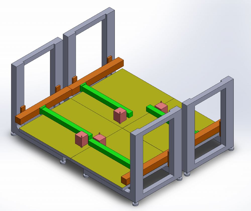 There should be no Limit of how many Printers can be joined together at least in a side by side format with two opposed Printers. Long structures can be built in short time. For example structure beams and maybe a Kayak.